Static Routing Lab
Before We Begin
For this lab, you’ll need the spoke1.img and spoke1.xml. You can follow this guide here:
Now that you understand the basics of static routing, it’s time for a real-world lab.
Note that this lab contains a lot more ambiguity and reliance on the student. Take your time and feel free to look up issues online as you find them. If you encounter an error, you cannot get around, you may contact a NEAT Administrator.
Our Project
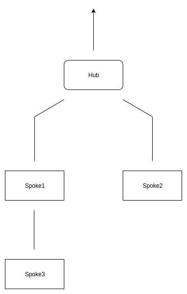
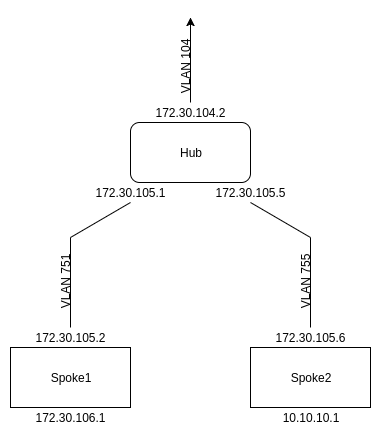
You work in IT for a law firm that is doing quite well. As a result, it has decided to open 2 new branches in 2 additional locations in the same state. Both branches need internet access, and they need to be able to talk to each other and the main office seamlessly. One option is to give both branches their own internet connections and use site-to-site VPNs to connect the branches. The company would prefer to consolidate all firewalling and internet filtering at the central HQ site, so they have decided to buy two metro ethernet links from the branches to the main office and connect them in a hub and spoke topology with one office branching off to another. It will look like this:
Setting up the Router
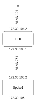
The hub will have access to 3 VLANs: the VLAN between it and the rest of the network, it and spoke 1, and it and spoke 2. For these VLANs, we will have only 2 hosts, so using a /30 (255.255.255.252) is appropriate. Due to existing infrastructure at the sites, we are forced to use quite a hodgepodge of IP addresses. Here are the IP ranges for each section:
Connection from hub to firewall: 172.30.104.0/30 (VLAN 104)
Connection from hub to spoke 1: 172.30.105.0/30 (VLAN 751)
Connection from hub to spoke 2: 172.30.105.4/30 (VLAN 755)
We are only setting up VLAN 104 for when we do firewall lab, so you’ll only be setting up the interface on the router.
Each of these spokes also has a dedicated LAN subnet that will be configured on an additional VLAN. These will only be configured on the host and spokes, so you don’t have to configure interfaces for these VLANs on the router.
Spoke 1 subnet: 172.30.106.0/24 (VLAN 106)
Spoke 2 subnet: 10.10.10.0/24 (VLAN 310)
This means your IP setup (between the hub and spoke 1) will look like this:
We Must First Add VLANs on Our Switch
Creating Vlans
We are going to create more vlans like we practiced during the Student Setup. Go ahead and create the vlans needed for this lab as mentioned above. If you need to, refer back to the Student Setup and follow the steps for the equipment you are using (Juniper or Cisco).
We Then Prepare a Trunk Port for the Router to Connect to
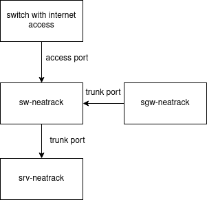
NOTE: If you went through the Student Setup Lab, you SHOULD have a configured at least one trunk port. When you went through the Student Setup Lab, you had the router connect via an trunk port for complete access to the switch/router. Your setup should currently look like the image below. If you are unsure, please reach out to your instruction for clarification and guidance.
Prepare the IRB/Sub Interfaces on the Router
To do the trunking, we will use logical interfaces, which can be referred to as an IRB interface if you’re using Juniper, or a sub-interface if you are using Cisco. Both are used to add IP addresses to vlans, which allow us to have multiple networks passed through a single port.
In the Student Setup Lab, you configured a logical interface for vlan60. You will now do the same for the vlans used in this lab. It’s up to you to follow the example from the Student Setup Lab and create sub-interfaces for all the other VLANs, including the hub to firewall VLAN (104).
Make sure to make a sub-interface for each VLAN. The router should be using the addresses 172.30.104.2/30, 172.30.105.1/30, and 172.30.105.5/30. (Remember that /30 is the same as 255.255.255.252!)
NOTE: For Cisco, if your interfaces have “shutdown” in their config they will not work. Type “no shutdown” to remove that rule from the sub-interface.
Remember to “write mem” or “wr”, otherwise if your switch or router turn off, they will lose any changes you have made. Remember to do this in the future too, this will be the last reminder.
Setting Up the Bird VMs
For this lab, we are going to be using very minimal Debian VMs for running Bird, an open-source routing protocol. You can do this by grabbing the spoke1.xml and spoke1.img files from the NeatRack fileserver.
First, we have to add the bridges to the host so we can feed them into the spoke1 VM. To do this, we edit /etc/network/interfaces on the host.
# spoke1 vlan
auto vlan751
iface vlan751 inet manual
    vlan-raw-device eth0

auto vmbr751
iface vmbr751 inet manual
    bridge_ports vlan751
    bridge_hello 2
    bridge_maxage 12
    bridge_stp off
    bridge_fd 9
    up /sbin/ifconfig $IFACE up || /bin/true
All we do here is pull the all the packets tagged for vlan 751 into the vlan751 interface. We then use that interface to make a vm bridge. Do the same for vlan 106. Remember that vlan 751 is the wan for spoke1 while 106 is its lan.
Note: for changes to /etc/network/interfaces to take effect you must do “ifup” and “ifdown” to each interface
We will be using virsh edit to modify the configuration files of VMs, but first we need to configure it to use nano for text editing. To do this, edit /etc/bashrc and add a line that says:
export EDITOR=nano
After that, run
"exec bash"
to apply the change.
Now, use “nano spoke1.xml” to edit the configuration file of spoke1 and find the network section. It should look something like this:
<interface type='bridge'>
  <mac address='52:54:00:08:14:2d'/>
  <source bridge='vmbr106'/>
  <model type='rtl8139'/>
  <address type='pci' domain='0x0000' bus='0x00' slot='0x05' function='0x0'/>
</interface>
For spoke1, we want to use two VLANs: one for the LAN (106) and the one for the WAN (751). You should remove the vmbr100 (or any other) bridge. Once added, the interfaces should look something like this:
<interface type='bridge'>
  <source bridge='vmbr751'/>
</interface>
<interface type='bridge'>
  <source bridge='vmbr106'/>
</interface>
Be sure that the slot numbers for each of the bridges are different as well, because you can’t have two interfaces with the same slot number which will cause a conflict.
You will also need to change to default source file to “/data/<image name>.img” so that you’ll be pulling from the correct image.
Finally, define the guest:
root@richweb-host 17:20:59
 > /data # virsh define spoke1.xml
We can now start our VM and console into it:
root@richweb-host 17:20:59
 > /data # virsh start spoke1

root@richweb-host 17:20:59
 > /data # virsh console spoke1
Virsh will automatically add the mac address, model, and address in for us, so we don’t have to worry about those. Now, boot up spoke1 and console into it. At the moment, it doesn’t have any usable network connections, so we have to add those. Before we can add a connection, though, we have to figure out which interface matches with which bridge.
To figure out which interface matches with which bridge, use the mac addresses. On spoke1, use “ip a” to find the mac address. In this example, the mac address would be 52:54:00:92:01:bf. Each ens# has a mac address – write them down, noting which belongs to each bridge. On the virtualization host, use “virsh dumpxml spoke1 | less” to view the xml configuration file for the spoke1 V to see which interfaces’ MAC addresses match with each bridge.
root@spoke1 17:20:59
 > ~ # ip a
1: lo: <LOOPBACK,UP,LOWER_UP> mtu 65536 qdisc noqueue state UNKNOWN group default qlen 1
    link/loopback 00:00:00:00:00:00 brd 00:00:00:00:00:00
    inet 127.0.0.1/8 scope host lo
       valid_lft forever preferred_lft forever
    inet6 ::1/128 scope host
       valid_lft forever preferred_lft forever
2: ens2: <BROADCAST,MULTICAST,UP,LOWER_UP> mtu 1500 qdisc pfifo_fast state UP group default qlen 1000
    link/ether 52:54:00:92:01:bf brd ff:ff:ff:ff:ff:ff        <------- on this line
    inet 172.30.106.1/24 brd 172.30.106.255 scope global ens2
       valid_lft forever preferred_lft forever
    inet6 fe80::5054:ff:fe92:1bf/64 scope link
       valid_lft forever preferred_lft foreverx
Now that you’ve matched up your bridges with your VM interfaces, write those down. You don’t want to forget which is which as you’re assigning IPs.
However, there is another way to easily match your interface/vmbrs with the appropriate MAC address. If you go back into the host and edit spoke1.xml, you can set the MAC address to contain the vmbr that you’re using. So for example, you can set vmbr 751 to have a MAC address of “52:54:07:51:00:00” The middle section is where you would put the vmbr so that when you are in the VM and run “ip a” you can figure out which interface matches to which vmbr.
In this example, we have figured out that ens2 is the LAN interface (VLAN 106), and ens5 is the connection to the hub (VLAN 751). Here is what our ens5 will look like in /etc/network/interfaces on the virtual machine, in this case spoke 1:
# Wan interface
auto ens5
iface ens5 inet static
    address 172.30.105.2
    netmask 255.255.255.252
    gateway 172.30.105.1
All this does is assign the IP 172.30.105.2 to spoke1 with a netmask of 255.255.255.252 and a next hop of 172.30.105.1. Do the same for the 172.30.106.0/24 network using the other bridge (in this case ens2) with spoke1 but without a gateway. As a reminder, be sure to do “ifdown” and “ifup” so your changes take effect.
Once the VM has its interfaces set up appropriately, you should be able to ping the hub’s IP (172.30.105.1) as well as its others and get responses. If you can do this, everything has been set up properly.
Routing and DHCP on Spoke1
Alright, now we’re done with all the base work. Now we can get on to the fun stuff: the actual routing and the DHCP server. Let’s start with the routing.
For routing, we’re using bird, an open-source routing protocol. It’s important to note that bird does routing and nothing else. Functionality that many people associate with a typical home “router” like NATting, firewalling, DHCP, and DNS is not done by bird. Bird accepts packets and them tells them where to go. Bird is great because it’s fast, easy, and supports all the most popular dynamic routing protocols.
Let’s start setting up bird. Bird works off of its configuration file in /etc/bird/bird.conf. Since all we need are a few static routes, our bird.conf will be very short.
At the top of our bird.conf, we are going to have these two lines:
log syslog all;
router id 172.30.105.2;
The first one logs all system events. The second one gives this router a unique identifier. Normally, you set this to the router’s public IP. In this case the public IP is 172.30.105.2. Next, we have the device section. In this, we just tell it to scan every 10 seconds to check if any of the information about the network interfaces has changed:
protocol device {
    scan time 10;
}
Next, the kernel section tells us what to do with the kernel’s routing table:
protocol kernel {
    persist;
    metric 64;  # Use explicit kernel route metric to avoid collisions
            # with non-BIRD routes in the kernel routing table
    scan time 20;
    import all;
    export all; # Actually insert routes into the kernel routing table
}
The kernel section isn’t particularly important until we implement some sort of dynamic routing, as all of these options are used for keeping track of dynamic routes. Put them in, but they won’t be important for now. Next, we have the direct section:
protocol direct {
    interface "ens5";
    interface "ens2";
}
This section autogenerates routes based off of the IPs of the interfaces. Finally, we have the static section:
protocol static {
    route 0.0.0.0/0 via 172.30.105.1;
}
This section tells all traffic other than that on the LAN interfaces to use the hub as the gateway.
similar to service networking restart bird can be restarted with service bird restart but that can cause unnecessary outages so that’s why we use “birdc configure soft”
Surprisingly enough, that’s all we have to do in bird. We do, however, have to edit a kernel module to make sure we can pass ipv4 traffic through the bird VM. This module is called net.ipv4.ip_forward and without it, no routing would work. To enable it, edit /etc/sysctl.conf and uncomment the “net.ipv4.ip_forward=1” line.
Now that routing’s out of the way, we can add DHCP. For this, we will use a simple ISC (Internet Systems Consortium) DHCP server. The configuration for this is all in /etc/dhcp/dhcpd.conf.
At the top of the file, we define the domain name and DNS server for all the DHCP clients.
option domain-name "local.test.spoke1";
option domain-name-servers 172.30.104.1;
Set the domain name as whatever is appropriate for you. We are using 172.30.104.1 (our firewall) as the DNS server for this example, but you can just as easily use something else like 8.8.8.8. Next, we get to the actual subnet-specific settings:
subnet 172.30.106.0 netmask 255.255.255.0 {
    range 172.30.106.100 172.30.106.200;
    option subnet-mask 255.255.255.0;
    option broadcast-address 172.30.106.255;
    option routers 172.30.106.1;
}
First, we define the network to use as 172.30.106.0/24. Next, we say that IP addresses will be distributed from 172.30.106.100-200. The subnet mask defines the size of the network, and the broadcast tells which hosts to broadcast requests to. Finally, we use the IP of the router as the router option.
Now, we just have to set a few basic rules and we’re done:
default-lease-time 600;
max-lease-time 7200;
authoritative;
The first two lines define how long to keep DHCP leases for. the default if 600 seconds, but if a client requests, it can go up to 7200 seconds. Authoritative says that this is the only DHCP serveron the network. That’s it for dhcpd.conf!
We need to make one last change and then we can test everything out. Open up /etc/default/isc-dhcp-server.
At the end, there should be a linke like the following:
INTERFACESv4=""
Add the LAN interface name in those quotes. Mine looks like
INTERFACESv4="ens2"
Note that yours might not be the same.
Now test the DHCP server with the command:
dhcpd -t
then proceed with the following commands:
service isc-dhcp-server restart
ifup and ifdown
birdc configure soft
If you get any errors, there is likely a syntax error in your configuration file. Run the suggested command and it should tell you what line the syntax error is on. After you fix it, make sure to use the respected command to which where the error was given.
You’re all done with the first spoke! Now we get to test the spoke to ensure it is working properly.
Testing
There are two main methods for testing this lab: with physical devices or VMs. I used two laptops connected to ports on my switch to make sure I could ping to and from every spoke and spoke LAN. If you didn’t have any hardware on hand to use, you could just as easily spin up 2 minimal guest VMs and connect them to the appropriate VLANs. I just like the laptop approach because I can physically see how the network is working. I won’t be going over how to test with VMs because I already described above how to connect a VM to a bridge. From there, everything is the same.
The only new part of testing is setting up the port for the laptop on the switch. For this example, I’m using port 21 and connecting it to the LAN VLAN for spoke 1.
richswitch#conf t
Enter configuration commands, one per line.  End with CNTL/Z.
richswitch(config)#int f 0/21
richswitch(config-if)#switchport access vlan 106
Now, just connect the laptop to the port and see if it gets an IP address. If it does, try pinging the spoke and the hub.
Troubleshooting Routing
Before you try to change anything, scroll up and make sure you edited all 4 files. A common error is incorrectly matching mac addresses, so review that too.
Try restarting the services on your spoke(s) to ensure all configuration changes are applied.
Here are a few common problems:
My device never gets an IP:
If this is the case, there is something wrong with either your DHCP server or your connection to the VLAN. Double check that you are plugged into the correct port and that your DHCP server settings are correct (make sure your KVM lab VM is started- you can use the “virsh list –all” command for this)
My device gets an IP starting in 169.254:
If this is the case, it means your computer can see it’s connected to a port, but it never receives an address via DHCP. Run “ps ax | grep dhcp” on your spoke to make sure the DHCP server is running. If it’s not, check /var/log/syslog for DHCP errors. If it is, you either have a bad configuration or have the wrong VLAN on the port your laptop is connected to.
My device gets the wrong IP (not starting in 169.254):
If this is the case, check your DHCP server settings. You may have a typo there.
I get an IP, but I can’t ping the spoke:
Make sure you have the spoke configured for the correct IP. If you got this far, you should be able to talk to the spoke.
Wait, I Did Everything Right. Why Can’t I Ping the Hub?
As we know, a router must have a next hop for all IP addresses passing through it. If it doesn’t have one, it will drop the packets. Then what did we do wrong with the router? We never gave it a route for the spoke1 LAN! Let’s add it in there and see if that fixes things:
trainrtr#conf t
Enter configuration commands, one per line.  End with CNTL/Z.
trainrtr(config)#ip route 172.30.106.0 255.255.255.0 172.30.105.2
Here, we just added a static route telling the router to forward all packets in the spoke1 LAN range to spoke1.
Now, you should be able to ping the router from the spoke1 LAN. If you can’t, make sure your bird configuration is correct and that you have added the net.ipv4.ip_forward=1 line to sysctl.conf. Also, make sure you can ping from spoke1 to the router and from spoke1 to the LAN.
Adding a Second Spoke
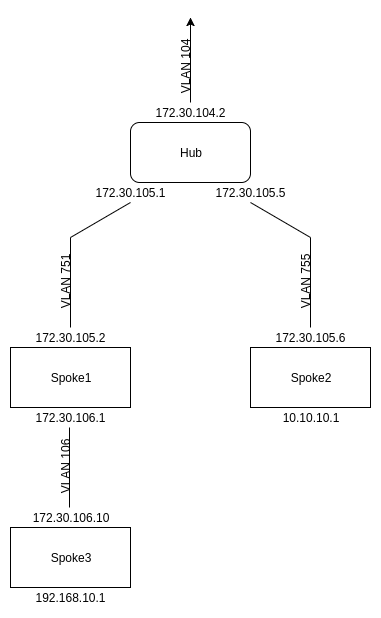
Now, this spoke1 to hub pinging is pretty cool, but it’s also pretty useless. There’s no reason to do this when we can just give spoke1 its own internet connection and cut out the hub. Well, it’s time to add a second spoke in there. We see a diagram of this below:
Spoke 2 will have a WAN address of 172.30.105.6/30 (VLAN 755) and a LAN address of 10.10.10.1/24 (VLAN 310). Make sure to create VLAN 310 on the switch and add on the virtualization host before doing anything more.
First, shut down spoke1. Now, we are going to use a new tool, virt-clone. This creates an exact copy of a VM Being able to clone like this is one of the big reasons why we use virtualization in general, and it comes in very handy on this lab.
root@richweb-host 22:24:20
 > ~ # virt-clone -o spoke1 -n spoke2 -f /data/spoke2.img
In this command, -o specifies what VM to copy from, -n specifies the new VM to create, and -f tells where to put the new VM image. Now that we’ve cloned the VM, we’re going to have to change the network interfaces on the second VM. Just as you did before, use virsh edit or nano to go into the VM delete the old interfaces, and add vmbr755 and vmbr310.
Startup spoke2 and console into it. You will notice that its hostname is still spoke1. To change that, edit /etc/hostname to ‘spoke2’ and restart the VM to apply it. Now that the VM has all the correct connections, you know what to do. Get to work changing all the configuration files. Here’s a list of files you will have to change:
/etc/network/interfaces – on both the virtualization host and the VM
/etc/bird/bird.conf
/etc/dhcp/dhcpd.conf (Make sure to change the domain-name from the previous DHCP server)
/etc/default/isc-dhcp-server (only if your interfaces swap which one is LAN and which is WAN)
Once these have all been changed appropriately, you can restart the services on the VM to apply all the changes. Lastly, don’t forget to add a route on the hub for the spoke2 LAN.
You can now test to see if everything’s working properly. To do this, connect two laptops – one to each spoke’s LAN. If they can ping each other, you’re in good shape. If not, look at the troubleshooting steps above.
Congrats! You’ve just completed a hub and spoke setup. Now, we’re going to take this lab a little further with a third (nested) spoke.
The Third Spoke
You’ve now created a fully functional hub and spoke setup with connection to the public internet. Now, however, your boss wants Wi-Fi in your warehouse. To support this separate Wi-Fi subnet, we’re going to add a spoke underneath spoke 1. This spoke will have its WAN address as 172.30.106.10 and its LAN subnet address as 192.168.10.1/24, as seen in the diagram below.
Create this third spoke with cloning just as you did the second. Don’t forget to create a VLAN (pick your own!) to use as spoke3’s LAN.
If, once you think you are done, you are still unable to ping outside of spoke3, do some pings to figure out where the packet is being lost. Make sure your packets have a route both to and from your destination.
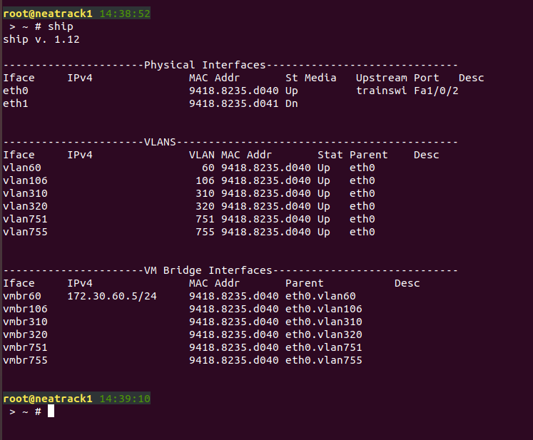
As a reference, this screenshot shows the general layout of the network interfaces on the host machine, showing all of the different VLANs and their interfaces. For this example, VLAN 320 is used as the LAN for the third spoke, but that can match up with whatever you chose. The DHCP server we set up in a previous lab is also running on the server on VLAN 60.