Dual-Stack BGP Lab
Before you begin this lab, make sure you have read the Introduction to IPv6 document for background on basic changes from IPv4 to IPv6.
This lab is also considered to be more advanced because of the scale and range of topics covered. Due to this, previously covered information, such as specific commands and configuration files, are not all going to be explicitly spelled out. Feel free to reference previous labs and documents if you need a reminder about how to configure something we previously introduced.
Lab Introduction
During this lab, we are going to be setting a network designed to imitate a small chunk of the internet backbone to show you how the internet works in connecting multiple Internet Service Providers and companies together. As explained in the BGP routing lab, Border Gateway Protocol is the dynamic routing protocol that serves as the backbone protocol for connecting data centers and ISPs together into an enormous routable mesh
There are two main types of BGP: iBGP (internal) and eBGP (external). eBGP is used when 2 Autonomous Systems (ASs) have routers that peer with each other so that they can send and forward traffic between each other. iBGP is what is used when a single AS has multiple routers that they manage and peer with each other so that traffic coming from eBGP can be sent forwarded throughout the internal network. In the previous BGP lab, you only configured eBGP to allow routers to route traffic between one another. With this lab, you will be configuring eBGP again, but you will also have one AS that has multiple routers and needs iBGP to allow traffic to pass between them.
The other main topic introduced in this lab is the idea of a Dual-Stack network. So far, all of our labs have dealt exclusively with IPv4, but with this lab we are going to be introducing IPv6. In the future, the goal is to have the internet exclusively work off of IPv6 and have IPv4 less and less used, but for the foreseeable future, both IPv6 and IPv4 are going to be very relevant. This means that many networks have shifted to supporting both IPv4 and IPv6 at the same time. This type of network is called a Dual-stack network, because bother versions of IP are functional and supported. With this lab, we’ll be showing you how to configure an IPv6 network that works in conjunction with the IPv4 you have grown to know.
Setting Up the Lab
To start the lab, go ahead and download a fresh copy of the Spoke1 image from online and configure the XML so that its name is bsn-gw-2. For right now, configure one network interface that can access the internet. If you are still using the VLANs from the Student Lab Setup, this means you should have the interface connected to “vmbr10”. Define and boot the bsn-gw-2 image, console in and get an IP address on your internet network with DHCP so that you can “ping google.com”. This will allow us to install a package that we need for setting up IPv6 on the Linux routers we will be using.
Run:
apt update; apt install -y radvd
This will install radvd, the daemon that we’ll configure so that the Linux routers send out Router Advertisements to hosts on the network.
Next, we want to make sure we enable IPv6 routing. If you don’t remember, we had to do this early on in the other routing labs, because by default forwarding is disabled by the Linux kernel. To do this, edit “/etc/sysctl.conf” and uncomment the line that looks like this:
net.ipv6.conf.all.forwarding=1
We are going to configure this router as a baseline image that’ll we’ll then clone and configure for the other routers in the network.
The Network
This is the diagram for the network that we are going to be configuring in this lab:
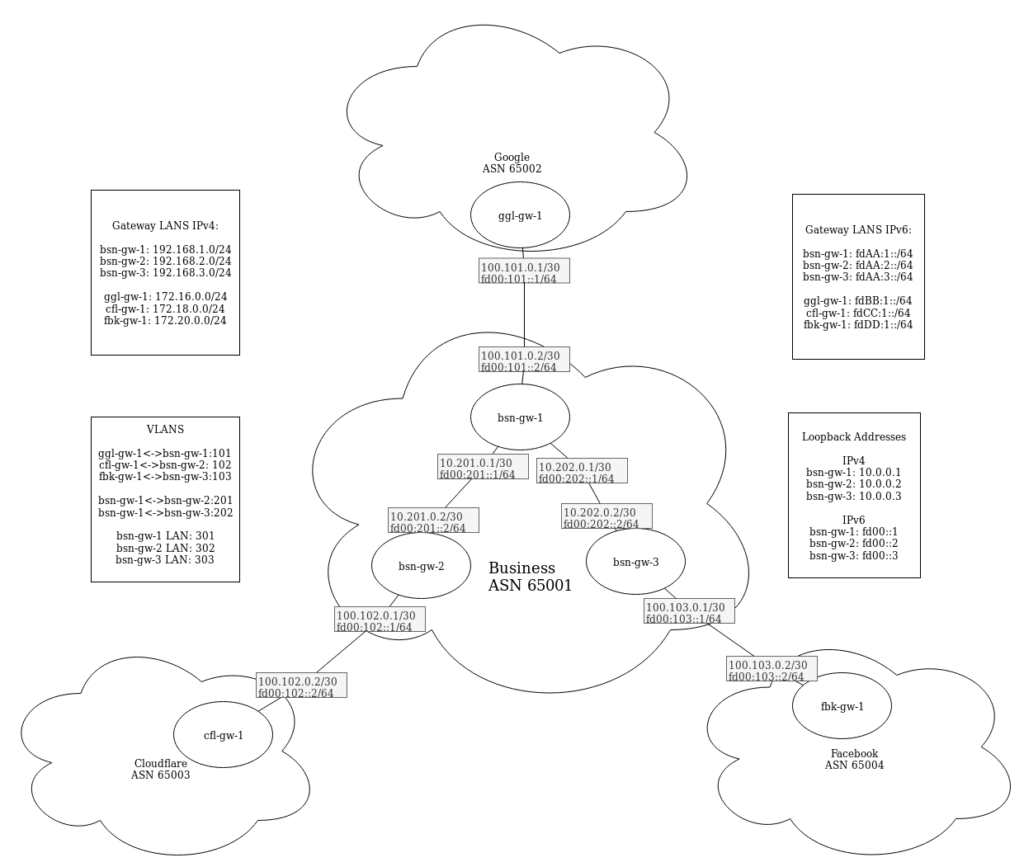
As you can see, you’ll be configuring 6 routers in total. 3 of which will be all “owned” by Business, which is where you’ll get to practice iBGP. Business is then peering with Cloudflare, Google, and Facebook through eBGP. Although this exact situation is far from ideal, seeing as there is there is only one path for any route in this lab, this sort of basic setup is essentially the building block for what the internet backbone looks like. In real life, there would be more routers and each router would have more peers, providing more redundancy, but for the sake of a lab, this covers what a basic BGP speaking network looks like. Also, Google, Cloudflare, and Facebook would each be peering with many other ASs who are also using BGP, meaning that by hopping from one AS to another, you can access the entire internet.
In order to configure this network, we are going to configure OSPF on all of the BSN routers so that they have dynamic routes to one another. Obviously in this network it would be easy to setup static routes between bsn-gw-2 and bsn-gw-3, but in a network that had more routers, you would use OSPF as an internal routing protocol.
Now, just because we are using OSPF doesn’t mean that we don’t use iBGP. OSPF enables all of the routers within BSN to talk to one another, but without iBGP, they would have no way of getting routes and forwarding packets that come from other ASs. What OSPF does allow us to do, however, is configure an iBGP peer between bsn-gw-2 and bsn-gw-3 despite them not being directly connected. This is called a multihop peer, because even though bsn-gw-2 and bsn-gw-3 will directly peer with one another, that traffic has to take a hop through bsn-gw-1 to form that communication. Multihop peers are unique to iBGP, because there shouldn’t be any sort of static routing or internal routing protocols that run between multiple ASs. Instead, peering between two ASs happens directly through a Point-to-Point network, which is typically done with fiber that is run between the locations.
When designing the lab, we used Bird routers for everything except for bsn-gw-1, so we are going to setup bsn-gw-2 first, clone it to bsn-gw-3 and make changes, then setup bsn-gw-1 as a Cisco router. This is designed so that you get experience using both BIRD and Cisco, but you could alter this if needed. Once all the internal routing is up and running, we’ll clone one of the Bird routers to make the Cloudflare, Facebook, and Google routers and initiate BGP one each of the routers so that we should be able to ping any router’s LAN from any other LAN.
In the context of this lab, we are going to pretend that any IP we use for LANs, so 192.168.0.0/16, 172.16.0.0/12, fd00:AA::/32, fd00:BB::/32, fd00:CC::/32, and fd00:DD::/32, are actually public IPs. Because we don’t have public IPs to play with, we’ll just be using these subnets, but in practice all of these LANs would be real public IPs that could be routed across the internet. Note that this doesn’t include any of the IPs we use for point-to-point connections or loopback addresses. Even in practice, those are typically private IPs that are just used for internal routing or creating peering sessions between routers.
Configuring bsn-gw-2
Network Interfaces
If you haven’t already, shutdown the bsn-gw-2 VM to setup all of the network interfaces. Go ahead and add all of the necessary vlans/vmbrs in /etc/network/interfaces on the host machine. These VLANs are 101, 102, 103, 201, 202, 301, 302, and 303 as mentioned in the diagram above. Then go ahead and remove the network adapter on the bsn-gw-2 you used for internet using “virsh edit”. Then add-in 3 network adapters for each VLAN bsn-gw-2 is attached to (102, 201, 302).
Start up the VM and console in. Make sure you change the hostname in /etc/hostname if you haven’t already. Next, we are going to start by configuring the network interfaces as we would normally, but this time we need to include a configuration for IPv6 since we are creating a dual-stack routing lab. Adding an IPv6 configuration is very simple and not much different from adding an IPv4 configuration. In my example, “ens5” is the interface directly connected to bsn-gw-1, so my configuration looks like this:
auto ens5
iface ens5 inet static
    address 10.201.0.2
    netmask 255.255.255.252
iface ens5 inet6 static
address fd00:201::2
netmask 64
Make sure you check which interface is connected to what–they should be in the same order you included them in virsh edit. Then add in an IPv4 and IPv6 address to each of the 3 interfaces based off of the network diagram. For the LAN interfaces, since this router will be the gateway, just give it the 1st address on the subnet. For bsn-gw-2, that means its addresses will be 192.168.2.1/24 and fdAA:2::1/64.
That configures the 3 virtual interfaces with both IPv4 and IPv6 addresses. After restarting the interfaces with “ipdown” and “ifup”, running “ip a” or “ship” will now show both the IPv4 and IPv6 addresses
Because we are using dynamic routing, we are also going to want to create a loopback address for both IPv4 and IPv6. This is done exactly the same way as with IPv4, just adding in an additional IPv6 address. Add these lines to the end of /etc/rc.local, only adjust the addresses as needed based on the network diagram:
/sbin/modprobe dummy
/sbin/ip link set name eth10 dev dummy0
ip address add 10.0.0.2/32 dev eth10
ip address add fd00::2/128 dev eth10
To apply this, either run the command “./etc/rc.local” (this just executes the script) or restart the vm (“/etc/rc.local” gets automatically executed on boot).
Routing
With all of the bsn-gw’s, we are going to be configuring both OSPF and BGP (both iBGP and eBGP), while we are only going to be using eBGP on the other 3 gateways, as in this lab they have no other local routers. As we did in previous labs, we are going to be using BIRD, but this time we are going to also need to use BIRD6 since we are creating a dual-stack environment.
BIRD 1.6, the current version used in the NEATRACK labs, has two separate config files for bird and bird6. The standard bird config, /etc/bird/bird.conf, is the one you’ve been using and will continue to use. Bird6 uses a separate config file located at /etc/bird/bird6.conf. In bird 1.6, IPv4 and IPv6 are two separate daemons, meaning that they don’t interact with each other at all and are configured entirely independently, so if one daemon stops, the other can continue to run and function normally.
We’ll start by configuring IPv4 in /etc/bird/bird.conf. The device, kernel, and direct protocols are all very similar to what you have seen in the past:
log syslog all;
router id 10.0.0.2;
protocol device {
scan time 10;
}
protocol kernel {
persist;
metric 64;
scan time 20;
import all;
export all;
}
protocol direct {
interface “ens2”;
interface “ens5”;
interface “ens6”;
interface “eth10”;
}
Now to configure OSPF. In my case, ens5 directly connects to bsn-gw-1, so I want to be communicating with OSPF on that interface. I then have my LAN configured as ens6, which I want to include in OSPF so that other routers know where the bsn-gw-2 LAN is, but it is configured as a stub since only hosts should be connected to the LAN. The loopback address is also included as a stubnet so that other local routers can ping the loopback address.
protocol ospf {
        import all;
        export none;
        tick 2;
        area 0.0.0.0 {
                interface "ens5" {
                        hello 6;
                        retransmit 6;
                        cost 100;
                        transmit delay 6;
                        dead 24;
                        type broadcast;
                };
                interface "ens6" {
                        stub yes;
                };
                stubnet 10.0.0.2/32;
        };
}
Next we have the filter setup to allow us to announce any local IPs in the 192.168.0.0/16 network. Remember that we are pretending those are public addresses, so with BGP we only want to announce public IPs. The next line then also allows us to reannounce any routes that are also learned through BGP. Without this, routers using BGP could only talk to networks 1 hop away, because the routes wouldn’t get shared with other peers. Finally, we reject anything else from getting advertised on BGP. This keeps private IPs from becoming routable across the Internet, which defeats the purpose of “private”.
filter lab_out {
        if net ~ 192.168.0.0/16 then accept;
        if source = RTS_BGP then accept;
        reject;
}
Last, we need to setup the actual BGP peers. Remember, you need one protocol for each peer. You’ll notice that there isn’t much difference between iBGP and eBGP configurations. Since we are using OSPF to create routes internally, we use the loopback address of each router with iBGP rather than a physical interface that could go down. This way, in a more connected internal network, there would be better redundancy with the BGP peers. As an added bonus, it also makes organization simpler when looking at an existing configuration.
Notice that we also change the source address. By default, BIRD would try to start a BGP connection from the closest physical interface to the neighbor. Since BGP checks the source address, though, we need to make sure it matches the expected neighbor IP for it to actually peer.
protocol bgp cfl_gw_1 {
        import all;
        export filter lab_out;
        local as 65001;
        neighbor 100.102.0.2 as 65003;
}
protocol bgp bsn_gw_1 {
import all;
export filter lab_out;
local as 65001;
neighbor 10.0.0.1 as 65001;
source address 10.0.0.2;
}
protocol bgp bsn_gw_3 {
import all;
export filter lab_out;
local as 65001;
neighbor 10.0.0.3 as 65001;
source address 10.0.0.2;
}
That’s it for the IPv4 configuration of BIRD. Luckily, the IPv6 configuration is very similar. Since we haven’t configured bird6 at all, the easiest thing to do is to actually copy the IPv4 configuration into the IPv6 configuration, then edit it as needed.
cp /etc/bird/bird.conf /etc/bird/bird6.conf
Then replace any IPv4 address with the appropriate IPv6 address in /etc/bird/bird6.conf. The one exception to this is the router ID: the router ID is going to remain an IPv4 address even when configuring IPv6, so just leave the ID as it is.
Once you have both configurations ready, run “service bird start” and “service “bird6 start”. If they are already running, you can reconfigure them with “birdc configure soft” and “birdc6 configure soft”.
You should now be able to check every protocol status in birdc/birdc6 with “show protocols all”. Since no other machines are up, nothing should be getting routes, but it should at least indicate that the protocols are running.
LAN Hosts Autoconfiguration
As mentioned in the intro to IPv6 document, autoconfiguration of LAN devices works quite a bit differently from how it does in IPv4. While in IPv4, all the information is provided by a DHCP server, IPv6 devices use Router Advertisements, SLAAC, and DHCP to set themselves up on the network. Since we are still using IPv4, go ahead and configure a DHCP server for bsn-gw-2’s LAN the same way you did in previous labs with IPv4.
Now we need to setup radvd on the router. This is what allows the Linux machine to send out Router Advertisements to the hosts on the LAN. To configure radvd, edit “/etc/radvd.conf” and configure it with this format:
interface ens6 {
    AdvSendAdvert on;
    MinRtrAdvInterval 60;
    MaxRtrAdvInterval 180;
    AdvDefaultLifetime 540;
    prefix fdAA:2::/64 {
    };
}
This configures the LAN interface (in my case ens6) to send router advertisements out. The Router Advertisements include the prefix for the LAN subnet. This tells the host which network to find an address on with SLAAC. The RA also automatically includes the link-local address for the router sending out the advertisement. This tells the host the IP for the router so that the host can setup a default route through the router.
This, by itself, is enough to get basic network functionality working with IPv6, but for most cases, we also need to setup DHCP for IPv6. DHCP isn’t needed for assigning IP addresses to hosts or telling hosts the default route, but other options still require DHCP to be autoconfigured by hosts. The most common of these is setting the DNS servers and domain, but just like with IPv4, there are many other options that can be used for sending information to hosts automatically.
We are going to configure the isc-dhcp-server to use IPv6 in addition to IPv4. Similarly to BIRD, isc-dhcp-server has two separate daemons for IPv4 and IPv6, but by default, doing “service isc-dhcp-server start|stop|restart” interacts with both daemons. First to enable IPv6 with DHCP, edit “/etc/default/isc-dhcp-server” and add in your LAN interface the same way you did with IPv4:
INTERFACESv6="ens6"
Then to configure the IPv6 server, edit “/etc/dhcp/dhcpd6.conf” and put in the following:
default-lease-time 600;
preferred-lifetime 7200;
authoritative;
subnet6 fd00:AA:2::/64 {
    option dhcp6.domain-search "business.local";
    ## Google's public DNS Servers--Equivelent to 8.8.8.8 or 8.8.4.4
    option dhcp6.name-servers 2001:4860:4860::8888, 2001:4860:4860::8844;
}
This should look similar to our IPv4 configuration, but notice that we don’t declare any ranges or IP addresses to hand out like we did with IPv4. This is because in this lab we just want to use SLAAC for getting addresses, but if needed, we could change radvd to tell hosts to use DHCP for addresses instead of SLAAC, then configure isc-dhcp-server to have a range of addresses to hand out, just like in IPv4.
That should be all of the configuration necessary for bsn-gw-2. Make sure that you have everything running with ifdown/ifup and birdc/birdc6 configure soft. For the DHCP server, test the configurations for errors with “dhcpd -t” and “dhcpd -6 -t” and if everything is fine, restart the isc-dhcp-server service. Once you have verified that everything is running, go ahead and test your LAN configuration. You can do this by putting a switch port on VLAN 302 and plugging in a laptop or putting a guest VM on the VLAN and getting an IP. Verify you got an address, and you can ping the router from both the IPv4 and IPv6 side (just using an IPv6 address with ping works).
Expanding the Network
Cloudflare GW
Now that you have a baseline image for your routers, let’s go ahead and create more routers on the network so we can start testing the different routing protocols.
Start by shutting down your bsn-gw-2 VM. Then clone bsn-gw-2 into a new VM called cfl-gw-1. We are now going to go through everything you need to change to prepare the VM for becoming a Cloudflare BGP router. Once it is cloned, edit your network interfaces with virsh edit and set the appropriate vmbrs. You’ll only need 2 for your cfl-gw.
Once you’ve done that, startup both VMs, console into cfl-gw-1, and edit these things as needed to adjust the settings for the new router:
/etc/hostname
/etc/network/interfaces (Follow the diagram for IPs)
/etc/rc.local
You can remove the loopbacks or change them to another address. Because we only use them internally with the Business network, they aren’t necessary for routing between eBGP sessions, but they can still be useful for setting a router ID.
/etc/bird/bird.conf and /etc/bird/bird6.conf
Change the router ID, direct protocol as needed, remove the OSPF protocol (since there is only one Cloudflare router), adjust the lab_out filter (allow Cloudflare’s LAN out), and finally setup the BGP peering session. There is only one peering session for Cloudflare, and that is directly with bsn-gw-2. Make sure you change the ASNs, and you set the neighbor IP as the IP of bsn-gw-2 on the Point-to-Point network (VLAN 102).
/etc/radvd.conf
Change the prefix to cfl-gw-1’s LAN
/etc/dhcp/dhcpd.conf and /etc/dhcp/dhcpd6.conf
Change the domain name and IPs as needed. You can leave the DNS server as Google’s since we aren’t using any sort of DNS servers internally (even though Cloudflare would never use Google for DNS :))
Finally restart everything and make sure it is running. Make sure you can ping bsn-gw-2 through their PTP VLAN. You can then use “ip r” and “ip -6 r” to view your routes. If everything is working with BGP, you should have routes to bsn-gw-2’s LAN IPs and be able to ping the router’s LAN IP.
Whether it is or isn’t working, you can test the BGP connection by running “birdc show protocols all name of protocol“. For example, on cfl-gw-1, you would run “birdc show protocols all bsn_gw_2” if that’s what you named it. (You can use birdc6 to view the same information on the IPv6 side). If everything is working, it should look something like this:
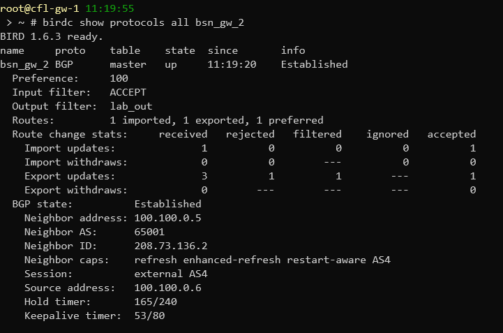
Note: The IPs above are different from the ones used in the lab
In the picture above, you can see that the “BGP State” is “Established”. This means that both routers have established a peering connection with each other and are able to exchange routes. If the state is “Active” this means that the router is actively looking to create a peering session but hasn’t been successful so far. If you see this, it means that something isn’t configured right. Make sure that both routers are running, they can ping each other, their BIRD configurations are set to use the right IPs and ASNs. It also might take a few seconds for the peering session to establish, but it shouldn’t take more than 20-30 seconds.
If your BGP session is established, but you still don’t have routes to the other router, check what it states under “Routes:” in the birdc command. In the picture above, there is 1 route being imported, another 1 route being exported, and 1 route (the 1 being imported) that is preferred. The one route being imported and preferred is the route to bsn-gw-2’s LAN. The route being exported is the route to cfl-gw-1’s LAN. If routes aren’t being exported on either router, that means that the route isn’t being sent through BGP. This could be because the direct protocol isn’t configured properly, or your filter is blocking routes from exporting.
In a scenario where we want to filter incoming routes, which protects against false routes from propagating across the internet, there could also be an issue where the import filter is blocking the routes being exported by another router. In this lab, though, we just accept all incoming routes, so that couldn’t be an issue in this case.
Once you have a successful peering session with bsn-gw-2 and can ping its LAN IP, move on to the next section.
Other Gateways
You can go ahead and follow those same steps for ggl-gw-1, fbk-gw-1, and bsn-gw-3. You can clone cfl-gw-1 too for the Google and Facebook routers since it is a much closer config that the Business routers. Make sure that for bsn-gw-3, you have OSPF setup and are peering with bsn-gw-1, bsn-gw-2, and fbk-gw-1. If you prefer, you can also setup bsn-gw-1 with BIRD to get it working, but the next section will go over how to setup bsn-gw-1 as a Cisco router. If you choose to use BIRD for bsn-gw-1, note that you are not entirely done, so not everything will be working exactly as expected. We’ll cover that later.
Now to configure bsn-gw-1 as a Cisco router. The easiest way of doing this will be to remove any current configuration you have (Maybe back it up with “show run” and copy it to a text document) and start from scratch. You can run “write erase” to clear the startup config and “copy startup-config running-config” to load the empty configuration. Then use the Cisco Lab to get a basic config on the router (you don’t need an IP address on fa 0/0). Then we are going to use some of the skills we learned in the Static and Dynamic routing lab to configure the router even further.
Let’s start with something basic: the Loopback IP address. You have done this before in the dynamic routing lab, but this config shows you how to add an IPv6 address to an interface:
interface Loopback1
 description BSN-GW-1 Loopback
 ip address 10.0.0.1 255.255.255.255
 ip ospf 1 area 0
 ipv6 address FD00::1/128
 ipv6 enable
 ipv6 ospf 1 area 0
As you can see, it is pretty easy to add an IPv6 address. I’ve gone ahead and also told the loopback interface to enable OSPF on it and to use the OSPF configuration with ID 1 on area 0. This way of configuring OSPF looks slightly different from how it was done in previous labs, but IPv6 only supports this format, so for consistency, we are using this way for both v4 and v6.
Go ahead and add 4 subinterfaces on the appropriate VLANs the same way you did in the static routing lab. Put on the appropriate IPv4 and IPv6 addresses and configure OSPF on the appropriate interfaces (not the one facing Google).
Now we’ll configure OSPF for IPv4 and IPv6. Since we already added the interfaces to OSPF 1, it is pretty easy to actually enable OSPF. Your IPv4 configuration should look like this:
router ospf 1
 router-id 10.0.0.1
 passive-interface FastEthernet0/0.301
 passive-interface Loopback1
While your IPv6 is literally exactly the same, just with IPv6. Remember that the router ID is still an IPv4 address though, even when using IPv6
ipv6 router ospf 1
 router-id 10.0.0.1
 passive-interface FastEthernet0/0.301
 passive-interface Loopback1
The next thing we need to configure is BGP on the Cisco router. This isn’t something we have done in previous labs, so here is the start of an example BGP config looks like:
router bgp 65001
 bgp router-id 10.0.0.1
 bgp log-neighbor-changes
 neighbor 100.101.0.1 remote-as 65002
 neighbor 10.0.0.2 remote-as 65001
 neighbor 10.0.0.3 remote-as 65001
 neighbor FD00::2 remote-as 65001
 neighbor FD00::3 remote-as 65001
 neighbor FD00:101::1 remote-as 65002
As you can see, we designate the local ASN when we create the BGP configuration with “router bgp ASN“. We then tell it the router-id and configure it to log any changes in the neighbors. Next, we list all of our neighbors–regardless of whether they use IPv4 or IPv6, as well as their ASN.
Similar to what we did with the BIRD routers since we are using our Loopback interfaces for iBGP, we need to tell BGP what source interface to use for the iBGP sessions. To do this, while still in the “router bgp 65001” config, add this config:
neighbor 10.0.0.2 update-source Loopback1
neighbor 10.0.0.3 update-source Loopback1
neighbor FD00::2 update-source Loopback1
neighbor FD00::3 update-source Loopback1
Notice we only configure the neighbors that are iBGP peers–we don’t use the loopback address for eBGP.
While you are still in the “router bgp 65001” configuration, we then need to configure which networks this router can advertise. These are separated by IP version, so to configure IPv4 networks we do this:
address-family ipv4
  network 192.168.1.0
And for IPv6 it looks like this:
address-family ipv6
  network FDAA:1::/64
Finally, we need to setup DHCP on the Cisco router. Router Advertisements are automatically set to go out when IPv6 is enabled on Cisco, so after DHCP, everything is done for the Cisco router.
To configure DHCP on IPv4, use this configuration:
ip dhcp excluded-address 192.168.1.0 192.168.1.100
ip dhcp excluded-address 192.168.1.100 192.168.1.255
ip dhcp pool IPV4_LAN
 network 192.168.1.0 255.255.255.0
 domain-name business.local
 dns-server 8.8.8.8 8.8.4.4
 default-router 192.168.1.1
 lease 7
and for IPv6, since we again aren’t leasing any actual IPs:
ipv6 dhcp pool IPV6_LAN
 address prefix FDAA:1::/64
 domain-name business.local
 dns-server 2001:4860:4860::8888
dns-server 2001:4860:4860::8844
And that’s it!
Troubleshooting
Don’t worry if you are having issues pinging–this is expected behavior and this lab will explain in more detail what is going on.
At this point, it seems as though everything should be working, and a lot of it is. Right now, all of your BGP peers should be in the “Established” state (you can run “show bgp all” to see BGP information on Cisco). Each of the routers should also have their LANs working with DHCP and autoconfiguration, and all of the Business routers should have OSPF working (if not the BGP peering sessions could go into the established state).
And, for the most part, any router should at least have a route to every other LAN. The first problem that you probably run into, is that this isn’t necessarily the case. If you check the routes on any of the non-business routers with “ip r” or “ip -6 r”, you should notice that you have an “unreachable” route to any of the other non-business LANs.
Then, checking the FIB with “birdc/birdc6 show route”, you get a very similar looking output for those routes.
The reason for this is due to one of the inherent differences between iBGP and eBGP. This specific difference is that the next hop doesn’t change when a route is learned through iBGP. That means that when, for example, bsn-gw-1 learns from bsn-gw-2 that it has a route to Google’s LAN, bsn-gw-2 doesn’t consider itself a valid next-hop to Google’s LAN. When bsn-gw-2 then shares that route with Cloudflare, the next-hop is still listed as bsn-gw-1, even though it doesn’t have a direct connection to bsn-gw-1. This invalid route is what causes the route to be “unreachable”.
In order to fix this, we have to tell the routers to set the next-hop to themselves with their iBGP peers. You’ll have to do this on all three Business routers for each iBGP peer on both IPv4 and IPv6. For the BIRD routers, add this line inside of every BGP protocol that uses iBGP:
next hop self;
An example protocol configuration should look like this:
protocol bgp bsn_gw_3 {
        import all;
        export filter lab_out;
        local as 65001;
        neighbor 10.0.0.3 as 65001;
        source address 10.0.0.2;
        next hop self;
}
Then for a Cisco router, you need to edit the address family configuration.
Enter the BGP config mode (“router bgp 65001”). Then enter the address family (“address-family ipv4/ipv6”) and add this command for each iBGP neighbor:
neighbor 10.0.0.2 next-hop-self
After you have made these changes to the configurations (including resetting BIRD), the routes should no longer be seen as “unreachable”.
Pinging Issues Due to Source IP
Even after all of those routes are fixed, however, you still might be running into problems with pinging some routers the way you expected, even if everything is working properly. The reason for this is inherent to the way that the network is designed. For example, let’s imagine the scenario where we are trying to ping bsn-gw-2 from ggl-gw-1. If we look at the route table on each of those routers, you can see that each of these routers have a valid route to each other’s LAN (192.168.2.0/24 for bsn-gw-2 and 172.16.0.0/24 for ggl-gw-1). The same is true for IPv6 too.
If both of these routers have a valid route to each other, why doesn’t a simple ping from one router to the other work? The reason for this is due to how ping, and a lot of other networking commands, work. When you run “ping 192.168.2.1” on ggl-gw-1, ggl-gw-1 automatically decides that the source address to include in the ICMP (ping) packet is the IP address directly attached to the next-hop. Looking at the routing table again, you can see that ggl-gw-1’s next-hop to reach 192.168.2.0/24 is 100.101.0.2, which means that the source IP used when you run the ping command is going to be 100.101.0.1. Remember that with BGP, we are only advertising routes to public IPs, while 100.101.0.0/32 is a private IP.
What that means for this scenario is that the ICMP packet being sent from ggl-gw-1 to bsn-gw-2 has a Destination IP of 192.168.2.1 and a Source IP of 100.101.0.1. DUe to the fact that ggl-gw-1 has a valid route to 192.168.2.1, the ICMP packet is actually reaching bsn-gw-2. The issue arises when bsn-gw-2 tries to issue a reply to 100.101.0.1, which bsn-gw-2 doesn’t have a route to and shouldn’t have a route to.
In order to get ping “working”, what we need to do is actually specify which source IP we want to use. For Linux, we do this with:
ping -I <source IP> <destination IP>
In the case of our scenario above, this would look like:
ping -I 172.16.0.1 192.168.2.1
For Cisco, the command requires a source interface rather than a source address, so the command looks like this:
ping <destination IP> source (source interface>
So, to ping cfl-gw-1 from bsn-gw-1, you’d use this command.
ping 172.18.0.1 source FastEthernet0/0.301