Dynamic Routing Using OSPF and BGP Lab
Before Getting Started
For this lab, you’ll need your spoke2 image with OSPF configured from the Dynamic Routing Using OSPF Lab.
Introduction
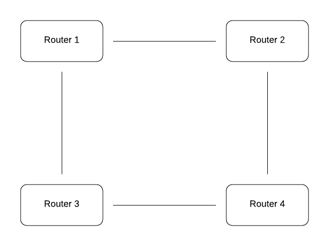
In the Dynamic Routing Using OSPF Lab, we configured OSPF on both Cisco/Juniper and Linux devices. In this lab, we’re going to eliminate the Cisco/Juniper devices and create a more complex network using OSPF and Linux KVMs – all within the host machine. In the static and dynamic routing lab, our spokes had just one external interface and one internal. For this lab, each router on the network will have two external interfaces along with one LAN, as shown below.
This part of the lab will simulate connecting Business Inc.’s four different offices together using OSPF.
Setup
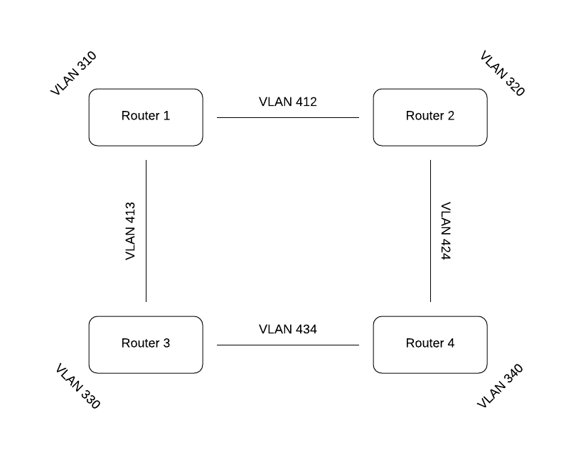
The only image we need for this lab is spoke2 from the dynamic routing lab. Go ahead and shut down all of your VMs. As the image above shows, each router has two external interfaces in addition to its LAN. As a result, we’ll need to add some bridges. Go into /etc/network/interfaces on the host and add (if it doesn’t already exist) a bridge just as you’ve done before for each of the following VLANs: 310, 320, 330, 340, 412, 413, 424, 434. the 3xx VLANs will be the four LANs for the routers and the 4xx VLANs will be the four connections between the routers. Don’t forget to “service networking restart” on the host when you’re done.
Virsh edit or nano spoke2 and add a third interface. Change the LAN interface to VLAN 320, and its two external interfaces to 412 and 424. Once that’s done, start and console into spoke2 and change its hostname to router2 in /etc/hostname. Shut down the VM. Next we’re going to rename the VM in virsh to avoid confusion using the following command:
virsh domrename spoke2 router2
That command renames the domain name of the VM from spoke2 to router2. Now that that’s done, start up and console into router2.
Getting Started
The first thing we are going to do with router2 is change its Router ID (RID) to 172.30.0.2. To do this, change the address in /etc/rc.local and both places in /etc/bird/bird.conf (the top line and the stubnet in “protocol ospf”).
Next, match interfaces (except eth10 – that’s the loopback dummy interface) by MAC address (comparing virsh edit router2 to “ip a” in router2) to determine which interface is LAN and which one is each external interface. You should write this down. For example, maybe “ip a” reveals ens2’s MAC address is 52:54:00:4d:27:20, which matches vmbr412 in virsh edit. In that case you would note that ens2 is on VLAN 412.
In /etc/network/interfaces on router2, change the LAN interface address to 10.10.20.1 (leaving the netmask as 255.255.255.0). For the interface on VLAN 412, set the address to 172.30.12.2/30 (/30 meaning netmask 255.255.255.252). be sure to remove the gateway address. add in the other interface (the one on VLAN 424) with address 172.30.24.1/30.
To add the interface to BIRD, go back to bird.conf and add in the new external interface to the “protocol direct” section. In the “protocol ospf” section, copy the configuration for the interface that doesn’t contain “stub yes;” (The WAN from when it was spoke2) for the other external interface. Make sure the LAN interface is the only one with “stub yes;” in its config.
Lastly, to configure DHCP, go to /etc/default/isc-dhcp-server and make sure INTERFACESv4 is set to the LAN interface. After that go to /etc/dhcp/dhcpd.conf. Change the domain name to “local.test.router2” and the subnet to 10.10.20.0/24. Pay attention to detail here, it’s easy to make a typo. Delete the domain-name-servers line. Once you’ve done that, reboot your VM and do “ip a” or “ship” to make sure each interface has the correct IP.
There should be four interfaces. If eth10 is missing, check rc.local. If any other interface is missing, check /etc/network/interfaces or even virsh edit the VM.
Make sure all the following commands show the services as active:
service networking status
service bird status
service isc-dhcp-server status
If some are down, check the configs in the corresponding files.
Expanding the Network
Now that you’ve set up one router, the hard part is done. The next step is to shut down router2 and make a copy for router1. You can do this using virt-clone or copying the image and .xml as explained in the Cloning Virtual Machines guide.
Once the copying is done, the steps to set up the new router are pretty straightforward. We will be configuring 3 more routers in the same way. The steps to set this up are listed below (in addition to being fully explained above). TIP: whichever interface is the LAN in your .xml file for router2, keep that same one for its copies so the LAN interface doesn’t change.
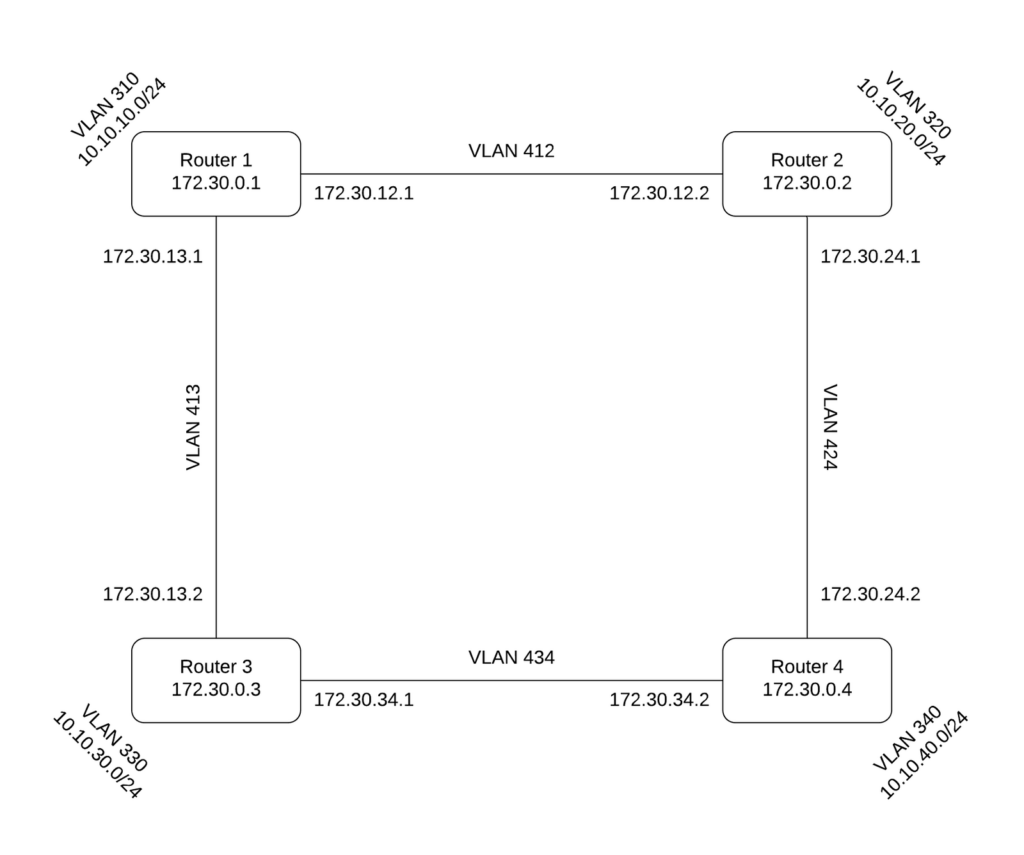
Information on IPs and subnets is in the diagram below this list.
Change the interfaces in virsh
Start up the VM
Change the hostname
Edit /etc/rc.local and /etc/bird/bird.conf (in both places) to change the Router ID
Edit /etc/network/interfaces according to the diagram (Matching MAC addresses)
Edit /etc/dhcp/dhcpd.conf to the appropriate LAN subnet
If the LAN interface changed:
Edit /etc/default/isc-dhcp-server
Edit /etc/bird/bird.conf to make the LAN network a stub.
Do this copying process 3 times so that you have a working network as shown below:
Testing
Be sure to restart ALL virtual machines before testing to make sure all configuration has taken effect. Additionally, wait about 30 seconds after boot to make sure OSPF has time to discover the other routers.
Once the network is done, each router should be able to ping both external interfaces and each loopback IP for every other router on the network. If this is not the case, make sure the interface not being broadcast is listed in “protocol direct” in bird.conf. If other issues persist, refer to the Troubleshooting section in the dynamic routing lab. (each router should have both wan and loopback listed expand that here)
Next, go into birdc on router1 and “show ospf topology”. You should see routers 2 and 3 with a distance of 100 and router 4 with a distance of 200. This is because 2 and 3 are one link away whereas router4 goes through two links, weighted as 100 each. Again, if this is not the case refer to the dynamic routing lab’s Troubleshooting section.
Now that everything’s working, we can demonstrate the usefulness of OSPF and its ability to dynamically redirect traffic. We’ll be testing using the “traceroute” command, which shows the hops a ping takes to get to its destination. Try using traceroute to ping router2 from router1. You should see something like this:
 > ~ # traceroute 173.30.12.2
traceroute to 172.30.12.2 (172.30.2122), 30 hops max, 60 byte packets
 1  172.30.12.2 (172.30.12.2)  0.568 ms  0.476 ms  0.408ms
Also do this for router2’s other external address (172.30.12.2). You’ll notice both addresses take just one hop, because the routers are adjacent in the network. Next, check which interface router1 uses to connect to router2 (the interface with IP 172.30.12.1 in “ship” or “ip a”). Do “ifdown <interface>”. Ifdown takes the interface down so it can no longer transmit data. After that, traceroute should reveal 3 hops – one for each other router. Thanks to the power of OSPF, the traffic is automatically redirected through the other routers to complete the connection. After you’ve confirmed this is working, do “ifup <interface> to re-enable the port.
In this example, traffic redirected immediately because router1 (pinging out) knew its interface was down. If we had disabled the interface connected to router1 on router2, it would take time to realize it was ‘dead’ before using the other path.
Stop and show your work to your teacher for grading.
BGP
We will be using all four routers for this part
This OSPF setup works just fine for connecting Business Inc.’s four offices. If they were four different companies, however, BGP (Border Gateway Protocol) would be used instead. OSPF is used only when all of the devices connected are owned by the same company. BGP is used when connecting different companies together and is used in the real world to connect data centers and large content service providers. Unlike with OSPF, companies use BGP when they only control one half of the connection–the routers they are forming neighbors with are owned by other companies and managed by different people. Similar to OSPF though, BGP is designed to share routing information dynamically to ensure fastest routes are chosen. BGP is a fundamental part of how the world is interconnected online.
We’re now going to assume that the four routers are now owned by different companies:
Router1: Business Inc.
Router2: Incorporation LLC
Router3: Cloud.io
Router4: WealthyNet Inc.

We’ll be connecting the four routers together in the same square pattern, but this time with BGP instead of OSPF.
First, comment out or delete your ospf configuration (You can comment it out like so /* commented code */).
Unlike OSPF, in BGP, you need a separate protocol for each interface. For example, router1 will need both
protocol bgp rtr2 {}
protocol bgp rtr3 {}
rtr2 and rtr3 are just names we’re giving the two of them – rtr2 will be the one connecting to router2, and rtr3 to router3.
Let’s look at the configuration for router1’s interface to router2 using BGP.
protocol bgp rtr2 {
    import all;
    export filter lab_out;
    local as 65001;
    neighbor 172.30.12.2 as 65002;
}
With “import all;” all routes from BIRD will be accepted by the machine. Export is using the following filter:
filter lab_out {
    if net ~ 172.30.0.0/16 then accept;
}
This filter ensures only external addresses will be advertised, so that the other companies won’t be able to ping into your internal network. Anything 172.30.x.x will be imported, but nothing else. In a real world situation, you’d handle this very differently, including likely having a firewall or some other similar configuration handle this. 65001 (“local as 65001;”) is the router’s Autonomous System Number (ANS). Like IPs, some ranges of ASNs (such as 64512-65534) are designated for private use.
Unlike OSPF, in BGP you define who your neighbors are. The neighbor IP is set to router2’s IP on VLAN 412, and its ASN is 65002. Router1 already knows router2’s IP on VLAN 412 because they are directly connected (refer to the diagram above). Router3’s ASN is 65003, and router4’s 65004. Using this information, we can now set up the other BGP protocols – two per router, in this case one for each interface.
The connection to router3 from router1 will be called rtr3 in router1 with the same import and export rules. Router1’s ASN is still 65001, so the “local as 65001;” line will also remain the same. The only line that changes aside from its name is the neighbor line. Use the IP of router3 on VLAN 413 (in the diagram above) and its ASN (65003) to set it as a neighbor of router1. It should look like this:
protocol bgp rtr3 {
    import all;
    export filter lab_out;
    local as 65001;
    neighbor 172.30.13.2 as 65003;
}
Restart the BIRD service and make sure it’s running. Router1 won’t have any neighbors right now, because the adjacent routers need to be configured to use BGP first.
That’s all there is to learn for this very basic BGP setup. Set up the other 3 routers the same way, with the export filter and two BGP protocols, one for each adjacent router. Once that is done, all routers should be able to ping all routers on either of their external interfaces.