OpenBSD Firewall with Tunnels Lab
Introduction
In the previous Firewall Lab, you set up a firewall that separated the Internet from the network you created. Besides firewalling, the OpenBSD virtual machine you created also used OSPF and translated the network addresses (using NAT) so that the packets could actually route out to the Internet.
In this lab, we will expand upon what can be done with a firewall by replacing Spoke 2 and Spoke 3 with firewalls that have the same functionality as before (DHCP server, routing, and OSPF) and then we will add to it later.
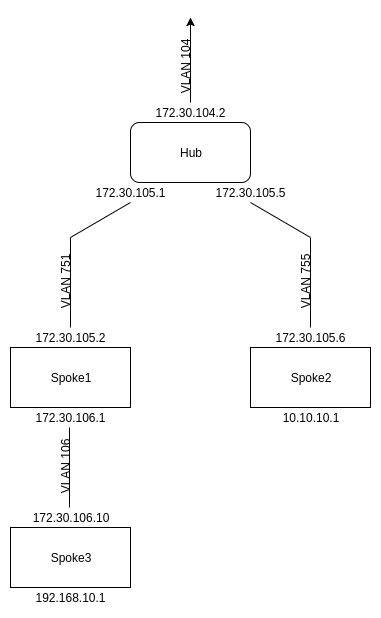
Your network setup should look like this:
Setup
Make sure that your network is fully functional with OSPF – a quick test would be pinging from Spoke 2’s LAN to Spoke 3’s LAN, as this traverses the entire network. This can be done either by connecting devices to the LAN, or could also be accomplished by specifying the source address when pinging:
ping -I 10.10.10.1 192.168.10.1
If this command was run on Spoke 2, it would send a packet with source address 10.10.10.1 instead of 172.30.105.6 destined for the LAN interface on Spoke 3. While this ping being successful does not guarantee your network is set up perfectly, it is a decent indicator that there aren’t major issues.
When you’re ready to begin, start by shutting down Spoke 2 as it will be replaced as well as the firewall so that you can copy it. Next, copy your existing firewall to a new one titled “fw-s2”using virt-clone (Reminder: virt-clone -o oldvmname -n newvmname -f /path/to/newimage.img). Once the copy has been created, be sure to use “virsh edit” to change the interfaces to match what Spoke 2 used before. The first interface should be the WAN, and the second should be the LAN. For convenience, you may choose to edit the last few characters of the MAC address to more easily distinguish between the internal and external interfaces.
With this setup complete, you turn back on your main fw-lab firewall as well as boot up your new firewall spoke2 image.
Configuring the Firewall
If you don’t remember the specifics on how to configure a file, please reference the previous firewall lab.
IP Addresses
Confirm that vio0 is the WAN interface and vio1 is the LAN interface. If not, you can shut down the VM and virsh edit it to swap which virtual bridge each interface uses.
Edit /etc/hostname.<interface> for vio0, vio1, and lo1 to reflect spoke2’s addresses.
Be sure to use “sh /etc/netstart <interface>” after editing a hostname file to ensure the changes are applied.
Edit /etc/interfacedb.txt to reflect the changes in VLAN number.
At this stage, ‘ship’ should show the correct IP addresses and VLAN IDs. If not, double check your work.
NAT
Since we want the functionality of this firewall spoke to mirror that of the spoke before, we don’t want to use NAT. Comment that out in the firewall configuration file /etc/pf.conf and use ‘fws’ to restart the firewall. If you get an error regarding an unused table, follow the instructions to resolve it.
OSPF
Edit /etc/ospfd.conf to ensure that OSPF is running on the WAN interface, and set the LAN interface to be a stub network (it should match the loopback interface).
To ensure the OSPF service will run, confirm ospfd_flags is defined in /etc/rc.conf.local. Once you’re done, use “/etc/rc.d/ospfd restart” to restart the OSPF service and apply the changes.
You will also need to add a firewall rule to /etc/pf.conf in order to pass OSPF traffic through the firewall. You should add this to every firewall on the network. 89 is the ip protocol number for OSPF
pass in proto 89 from any to any
At this step, the firewall spoke should be a neighbor to the router via OSPF just like the spoke was before and should be fully connected to the network. If not, double check your work and do plenty of testing with ping to locate and debug the issue. You can use “ospfctl ?” to see information about OSPF for use with debugging and/or confirming neighbors. If you confirmed your network was fully functional before starting this lab, you know the issue must be with the configuration of this firewall spoke.
DHCP
Since this firewall is replacing the previous spoke, you will need to set this firewall up as a DHCP server in its absence. The configuration should be identical to what it was before – since spoke2 is now shut down, you can use spoke1 for reference as you wish. If you’d prefer to read documentation, DHCP configuration was explained in the Static Routing Lab.
Unlike on the Linux VMs, this dhcpd.conf file does not already exist on the firewall and should be created at /etc/dhcpd.conf. There is an example config in /etc/examples that you can copy into the /etc directory so that we don’t have to completely make it from scratch. No changes to any isc-dhcp-server file are needed.
To ensure the DHCP service will run, define dhcpd_flags=”vio1” in /etc/rc.conf.local. This specifies that the DHCP server should only run on vio1, the LAN interface. Once you’re done, use /etc/rc.d/dhcpd restart to restart the DHCP service and apply the changes.
At this step, the firewall spoke should be a DHCP server giving out IP addresses on its LAN subnet. You can test this by connecting a physical device to a configured switch port, or by using a virtual machine guest. If you wish to use a guest, just ensure it has an interface using the same virtual bridge as the LAN interface on the spoke so that it’s on the same VLAN. You can use dhclient <interface> to manually request an IP address on an interface and dhclient -r <interface> to release it.
Again?
Now that Spoke 2 has been replaced, you’re ready to repeat the same process with Spoke 3, so go ahead and shut it down. To save yourself the time of reconfiguring rc.conf.local and /etc/dhcpd.conf, you should shut down fw-s2 and virt-clone it (see above) to fw-s3. Repeat the exact same steps as above, starting with Setup, referencing the network diagram to ensure you’re now using Spoke 3’s IP addresses and VLANs. Once you’ve done that, and you’ve confirmed everything is properly interconnected (you can ping), you’re ready to move on to the next phase of the lab!
Troubleshooting
Did you forget to shut down the spoke you are replacing?
OSPF troubleshooting in the firewall: “ospfctl ?”
OSPF troubleshooting in Cisco router: “show ip ospf ?”
Firewall Tunneling
Introduction
Tunneling is the process of creating a logical ‘tunnel’ through which traffic travels – while the packets still travel across the same physical network, one can use abstraction to think of it as if there is a tunnel connecting the two. Just don’t forget that since there isn’t a physical tunnel, it can’t be used as a failover (a backup) if a connection goes down.
Tunneling is accomplished through what is known as encapsulation, which is the process of putting a packet inside of another packet. With a tunnel connecting fw-s2 and fw-s3, packets travelling from inside fw-s2’s LAN to fw-s3’s LAN are put inside another packet (from: fw-s2’s WAN, to: fw-s3’s WAN). On its own, this doesn’t accomplish much, as the contents of the packet are still visible, but setting it up in this way allows for encrypting the encapsulated packet, making it so that devices connecting the two firewalls see nothing but encrypted traffic traveling between them, with no idea of which devices on their LANs are communicating.
To set up firewall tunneling, both ends of the tunnel will need a dedicated interface – we will use gre# for naming them. We will start by creating a tunnel between fw-s2 and fw-s3. To do this, we will have to follow the same steps on both ends of the tunnel, and we will start with fw-s2.
Creating the Interfaces
To begin, we will create a new interface gre0 by putting the following information in /etc/hostname.gre0:
172.30.107.1 172.30.107.2 netmask 255.255.255.252 link0 up
tunnel 172.30.105.6 172.30.106.10
!route add 192.168.10.0/24 172.30.107.1
172.30.107.1 and .2 are two IP addresses we arbitrarily chose to represent the two ends of the tunnel, defined on a /30 network (255.255.255.252).
The two IPs on the ‘tunnel’ line are the start and end points of the tunnel – starting at fw-s2’s WAN IP and ending at fw-s3’s WAN IP.
The route we’re adding tells the machine that traffic destined for Spoke 3’s LAN should be sent to its tunnel IP address (encapsulated in the tunnel) instead of travelling normally across the network.
And Back Again
Next, use the same steps but with flipped IP addresses to set up GRE on fw-s3. Remember that fw-s3 is 172.30.107.2 connecting to 172.30.107.1 (fw-s2). You’ll have to swap the ‘tunnel’ IPs and change the route to be fw-s2’s LAN via fw-s2’s LAN IP (makes sense, right?).
Testing
Try pinging from fw-s2’s LAN to fw-s3’s LAN, using either a machine connected to it or with
ping -I 10.10.10.1 192.168.10.1
You would expect to be able to send traffic from fw-s2’s LAN to fw-s3’s LAN, but you can’t! Why? The firewall is blocking the gre packets, so they never travel across the network.
Fixing
To fix this, you’ll have to edit /etc/pf.conf and add a rule allowing gre packets.
pass on $ext_if inet proto gre
This rule allows packets travelling across the external interface to pass through if their protocol is gre, enabling our tunnel to work.
You should now be able to ping from one LAN to the other again. If not, double check your work. Ping is your friend!
You will also notice that you are no longer able to ping the Internet (no further than fw-lab). This is because we haven’t yet added the tunnel IPs to the list of IP addresses fw-lab is NATting so the packet source remains unchanged, and the next router upstream doesn’t know what to do with it. To fix this, simply add 172.30.107.0/30 to the list of IP ranges to NAT.
This tunnel setup is neat, but we haven’t provided any security yet. If you tcpdump the data passing through, you’ll see the packet is still visible, just encapsulated in another packet. To fix this, we’ll encrypt the data using IPsec which encrypts the data we’re sending, which is similar to how a VPN works.
Establishing IPsec
To set up IPSec, put this information in /etc/ipsec.conf
key="15.learner"
ike active esp transport from 172.30.105.6 to 172.30.106.10 \
 main auth hmac-sha1 enc aes-128 group modp1024 \
 quick auth hmac-sha1 enc aes-128 group modp1024 lifetime 28800 psk $key
This complicated one-line configuration command (the backslashes split it among multiple lines) specifies the ‘from’ and ‘to’ IPs, along with specifications about the encryption method. The last part uses the ‘key’ variable defined above – a variable is used instead of directly entering the password both for readability and in case multiple different tunnels are configured with the same password.
You will also need to add this information to /etc/rc.conf.local so that IPsec starts and to configure its startup flags.
ipsec=YES
isakmpd_flags="-K -4"
-K signifies that it won’t load the keynote policy, and the -4 specifies that we’re using IPv4 traffic
Remember to restart the ipsec.conf file by running the following command:
/etc/rc.d/isakmpd restart
Next, do the same IPSec setup steps for the machine at the other end of the tunnel.
Testing
Try pinging from fw-s2’s LAN to fw-s3’s LAN, using either a machine connected to it or with
ping -I 10.10.10.1 192.168.10.1
You would expect to be able to send traffic from fw-s2’s LAN to fw-s3’s LAN, but you can’t! Why? Surprise, firewall again.
Fixing
Allow IPsec’s protocol number, which is 50 through the firewall the same way you did GRE earlier and it will allow the traffic through.
You should now be able to ping from one LAN to the other again. If not, double check your work. Ping is your friend!
This tunnel now makes it so that any traffic travelling between fw-s2 and fw-s3 is encapsulated and encrypted, adding security to that connection. While this isn’t a huge deal on a small network, if this tunnel were to be across the Internet or if this were used on a larger network then the added security and encapsulation would be very helpful.
Your Turn Again
Make an IPSec-encrypted tunnel between fw-s2 and fw-lab. This means that all the devices between fw-s2 and fw-lab will not be able to understand or decode the traffic they are passing between them.
To do this, you will need a new interface gre1 on fw-s2 and to create gre0 on fw-lab. After that, you will need to add another IPSec configuration line to the existing file (no need to repeat key= since it will be the same). For steps on how to do this, see above. Note: Be sure to pick a different /30 subnet on which to make the tunnel. For organization’s sake, you could consider subnet right after the 172.30.107.0/30 network. If you aren’t sure what that is, review the IP Addressing document and the Static Routing Lab.
There is one extra change that will be made to the tunnels leading to fw-lab: We will make them the default route, so that traffic is routed to them by default. To accomplish this, we will add the default route on fw-lab’s gre interface for this tunnel. Add this to the bottom of the interface’s config (/etc/hostname.<interface>)
!route add 0.0.0.0/0 <fw-lab corresponding gre tunnel ip>